Nicht kategorisierte Dateien
Zur Navigation springen
Zur Suche springen
Unten werden bis zu 50 Ergebnisse im Bereich 4.201 bis 4.250 angezeigt.
-
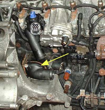 Kuehlsystem Thermostat Einbauort 5Zyl.jpg 400 × 419; 84 KB
-
 Kuehlsystem Thermostat Einbauort 6Zyl.jpg 800 × 600; 79 KB
-
 Kuehlsystem Thermostat Funktion.jpg 350 × 430; 55 KB
-
 Kuehlsystem Thermostat TDI Bild.jpg 300 × 264; 50 KB
-
 Kuehlsystem Thermostat Wechsel AAC Befestigungsschrauben.jpg 500 × 375; 73 KB
-
 Kuehlsystem Thermostat Wechsel AAC entnommen.jpg 500 × 375; 62 KB
-
 Kuehlsystem Thermostat Wechsel ACV Befestigungsschrauben.jpg 800 × 600; 155 KB
-
 Kuehlsystem Thermostat Wechsel AES Schrauben Reglergehaeuse.jpg 800 × 600; 79 KB
-
 Kuehlsystem Thermostat Wechsel AES Schrauben Reglergehaeuse2.jpg 600 × 800; 95 KB
-
 Kuehlsystem Thermostat Wechsel AES zerlegt.jpg 800 × 600; 84 KB
-
 Kuehlsystem Ventil N214 Bild.jpg 500 × 500; 45 KB
-
 Kuehlsystem Ventil N214 Einbauort Magnetventil TDI.jpg 500 × 375; 70 KB
-
 Kuehlsystem Ventil N214 Einbauort Ventil TDI.jpg 500 × 375; 78 KB
-
 Kuehlsystem Ventil N214 Funktion.jpg 650 × 414; 50 KB
-
 Kupplung Hydraulik 02B Entlueftungsventil.jpg 800 × 600; 78 KB
-
 Kupplung Hydraulik 02B Nehmerzylinder Einbauort.jpg 800 × 600; 82 KB
-
 Kupplung Hydraulik 02G Entlueftungsventil.jpg 800 × 599; 91 KB
-
 Kupplung Hydraulik 02G Nehmerzylinder Bild.jpg 800 × 600; 49 KB
-
 Kupplung Hydraulik 02G Nehmerzylinder Einbauort.jpg 800 × 600; 95 KB
-
 Kupplung Hydraulik 02G Nehmerzylinder Einbauort alt.jpg 521 × 600; 90 KB
-
 Kupplung Hydraulik 02G Ventileinheit Einbauort.jpg 800 × 600; 87 KB
-
 Kupplung Hydraulik Entluefter Spiel.gif 800 × 600; 366 KB
-
 Kupplung Hydraulik Geberzylinder Anschluesse.jpg 800 × 600; 100 KB
-
 Kupplung Hydraulik Geberzylinder Befestigung.jpg 800 × 600; 96 KB
-
 Kupplung Hydraulik Geberzylinder Bolzen.jpg 800 × 600; 99 KB
-
 Kupplung Hydraulik Geberzylinder Einbauort.jpg 800 × 600; 93 KB
-
 Kupplung Hydraulik Geberzylinder Entluefter.jpg 800 × 600; 202 KB
-
 Kupplung Hydraulik Geberzylinder Halter defekt.jpg 600 × 800; 189 KB
-
 Kupplung Hydraulik Geberzylinder Halter defekt Keil.jpg 800 × 600; 151 KB
-
 Kühlsystem Kreislauf Schlaeuche WT vorne.jpg 800 × 600; 90 KB
-
 Kühlsystem Kreislauf basis 75 Geber.jpg 800 × 661; 97 KB
-
 Kühlsystem Kreislauf basis 75 gross.jpg 800 × 661; 108 KB
-
 LLK02web.jpg 500 × 343; 94 KB
-
 Laborbetrieb climatronic.png 1.776 × 1.037; 641 KB
-
 Lage sechs Klammern.jpg 3.024 × 4.032; 1,37 MB
-
 Lage sechs Klammern 2.jpg 3.024 × 4.032; 1,29 MB
-
 Lage sechs Klammern 3.jpg 3.024 × 4.032; 1,5 MB
-
 Lage sechs Klammern 4.jpg 4.032 × 3.024; 1,62 MB
-
 Lambda sond till volvo240 etc.jpg 800 × 413; 60 KB
-
 Lambdasonde-Diagnosebild-im-AAC-ab-Baujahr-03-1992.jpeg 2.074 × 1.530; 782 KB
-
 Lambdasondennuss 3337.JPG 4.096 × 3.072; 2,29 MB
-
 Langenaltheim12Oktober2008 (47).jpg 2.128 × 2.800; 1,15 MB
-
 LeM.jpg 1.000 × 807; 1,43 MB
-
 Lenkschloss.jpg 1.000 × 565; 399 KB
-
 Lenkstockschalter Abdeckung.jpg 174 × 198; 13 KB
-
 Lenkstockschalter Grundplatte.jpg 352 × 195; 19 KB
-
 Lenkstockschalter Grundplatte1.jpg 338 × 198; 25 KB
-
 Lenkstockschalter Hebel.jpg 334 × 198; 13 KB
-
 Lenkstockschalter Schraube.jpg 352 × 194; 15 KB
-
 Lenkstockschalter Testmontage.jpg 111 × 198; 9 KB


